Geofence Application: Wiring
Because the RS232 shield requires a 5v supply we need to make sure that this is selected on the WiFire. JP9 allows a jumper to be placed on either the 5v0 pin and a center pin or the 3v3 pin and center pin. This header can be found next to the power supply headers (reset, 3v3, 5v, GND, GND, Vin). Make sure that the jumper connects 5v0 to the center pin.
Pin Selection and 5v tolerant I/O
We have now provided the RS232 shield's required 5 volts. The WiFire however operates at 3v3 (3.3 volts), but it does have 5v tolerant IO.
In order to work with this shield we will need two things:
- The ability to provide a logic HIGH or ON signal. This is used for sending data.
- The ability to receive a logic HIGH of 5v from the shield, without damaging the WiFire
While for this project we do not require sending data through the shield, I will cover it for completenesses sake.
Reading the MAX232 datasheet we can see in table 7.3 that V_IH, the High-level input voltage has a minimum value of 2v. This means that our 3.3 IO ports will be able to deliver the required HIGH.
For receiving data we can see that the MAX232 will output above 3.3v, so to avoid damage to the WiFire we need can use a 5v tolerant IO.
The RS232 shield allows, via the use of jumpers, itself to be configured to use any pins from 0-7 on Arduino/Arduino compatable boards for either receive or transmit.
In order to interface with the RS232 shield we need to use UART. The WiFire has 6 UART modules, each able to be mapped to several IO pins through the Peripheral Pin Select (PPS) system. Ideally we would like to find a UART module that can be mapped to compatible pins (e.g. 5v tolerant RX pin) within the range of 2 and 7 (0 and 1 are used for serial output by Serial.println).
It so turns out that UART module 6 can be mapped in such a way, and is implemented under Serial2 in our modified MPIDE. In order to use it we will use the PPS functions to map the module to the pins that we desire.
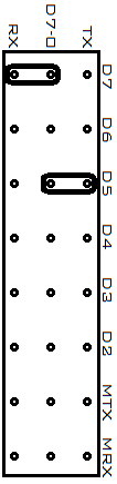
For the RX pin we will use pin 5, a 5v tolerant pin. For TX we will use pin 7. To configure this wiring on the RS232 shield we need to connect the jumpers so that D5 connects to TX and D7 to RX. This may seem backwards, but remember that from the WiFire's perspective D5 is for receiving on, but from the shield's perspective D5 is for transmitting to.
The jumper positions can be seen illustrated in the diagram below.
On the WiFire in order to map D5 and D7 we can issue the following in setup()
mapPps(5, PPS_IN_U6RX);
mapPps(7, PPS_OUT_U6TX);
Note that even if there were no UART modules able to be mapped to the desired pins, it would still be possible to use the pins for serial communication through the Arduino library SoftwareSerial.
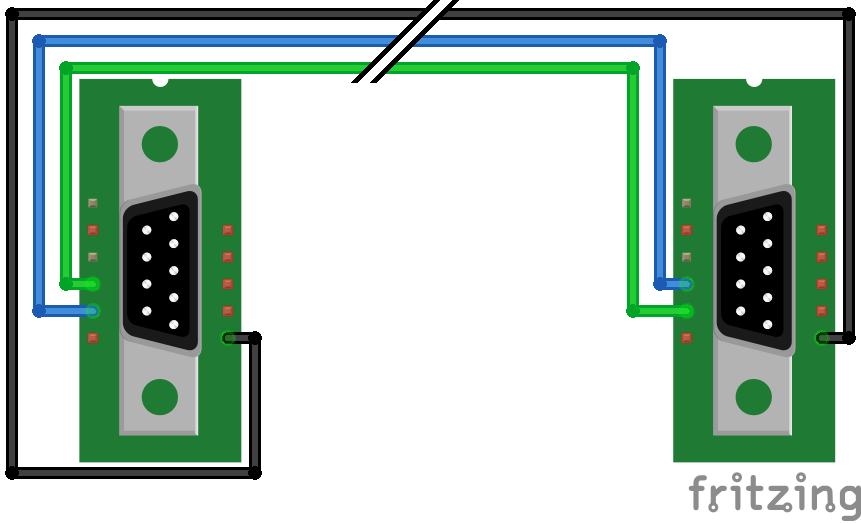
DB9 Crossover cable
As with connecting the shield to the WiFire, we need the RS232-Bluetooth's RX (or RD) to connect to our shields TX (or TD) and vica-versa. We will achieve this by creating a cable with a male DB9 plug at each end, wired to connect each plug's RX to the other's TX. The cable will also connect the GND pins to create a common ground. All other pins can be safely ignored.

Now after connecting everything up, everything looks like this.
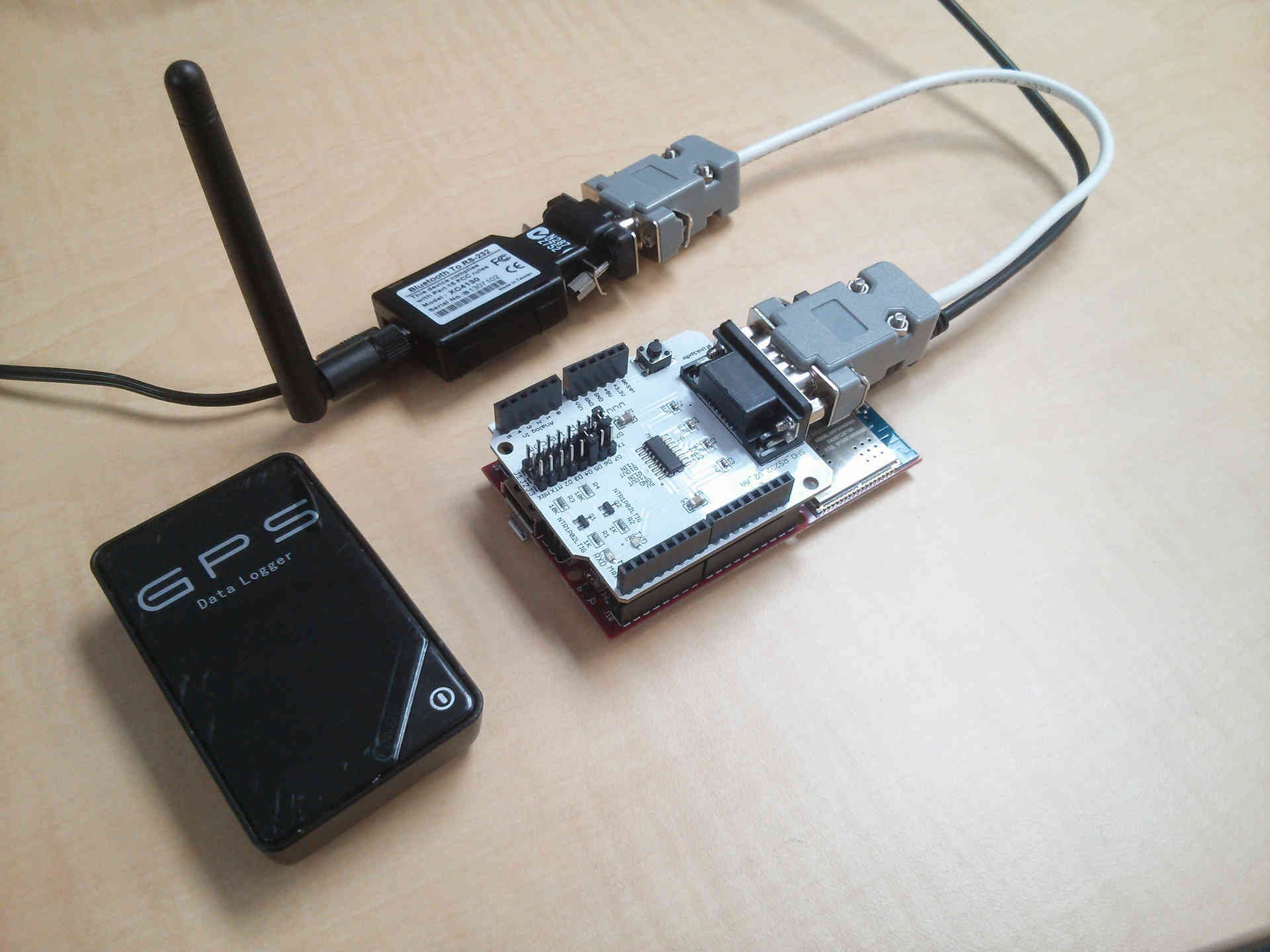
It's time to move on to test if we can get data back from the GPS.